Timing Is the Spec: Synchronisation Requirements for Robot-Learning Capture Hardware
What 'synchronised' actually means for egocentric rigs, trackers and multi-camera systems, the targets frontier robot-learning teams specify, and the acceptance test that proves a device meets them.
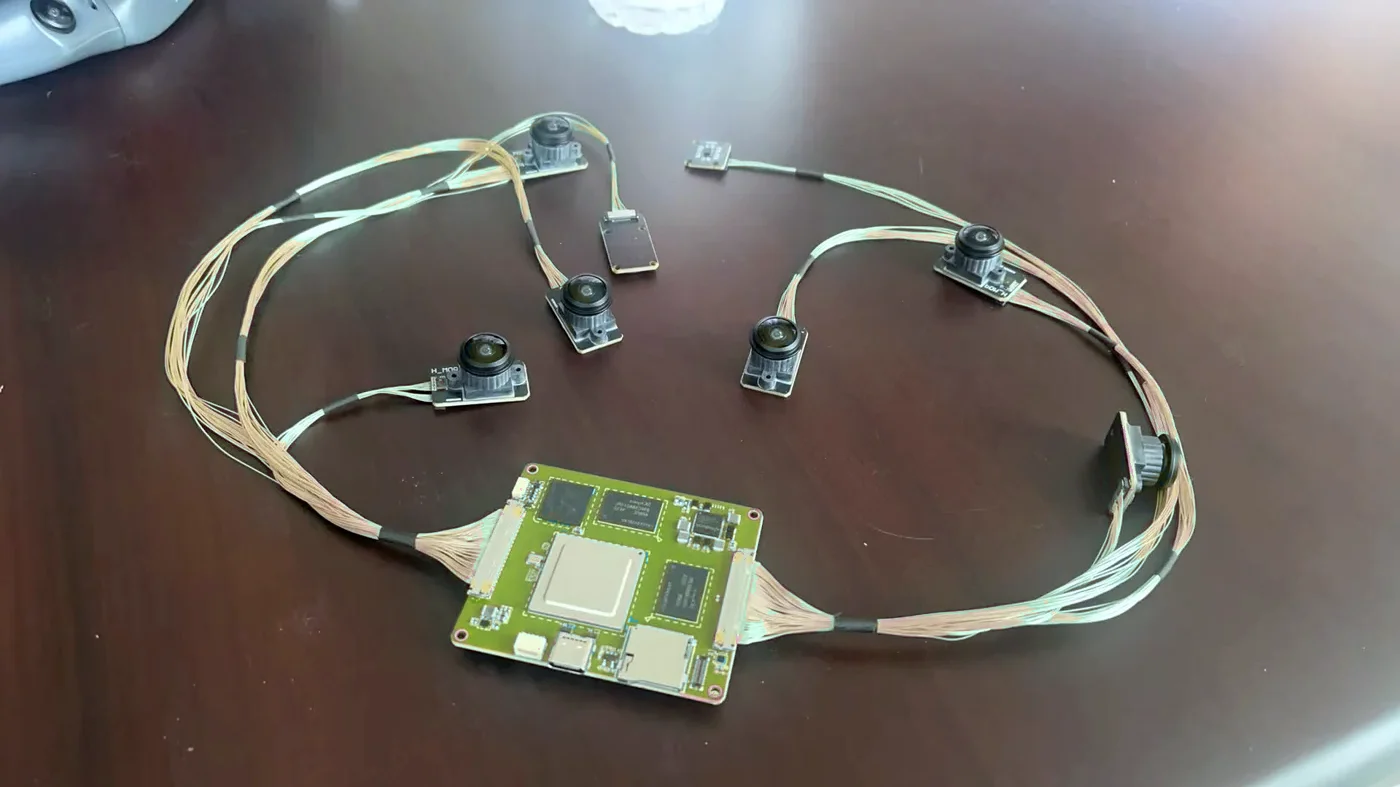
For robot-learning capture, 'synchronised' must mean that every sample carries the time its light or motion was actually acquired, on one shared clock. Practical targets used by frontier teams are under 100 µs between tracking cameras, under 500 µs camera-to-IMU, and under 1 ms for RGB and radio events — verified by measurement, not vendor statements.
In our 2026 vendor evaluations, most egocentric devices marketed as 'synchronised' timestamped frames on the host or claimed millisecond-level alignment; very few documented where the timestamp originates.
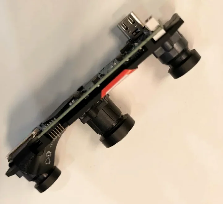
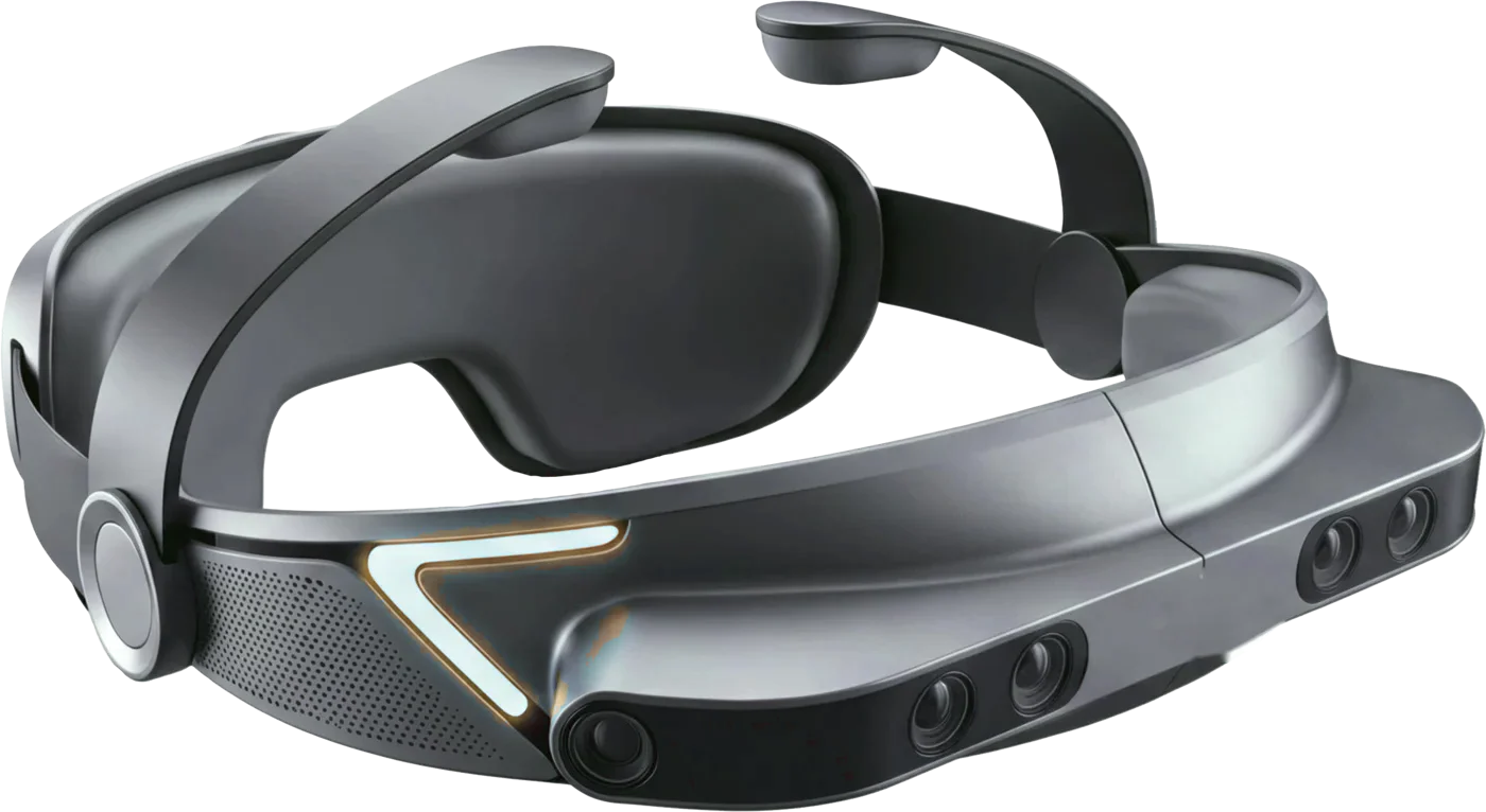
Robot foundation models learn from the relationship between what a camera saw and what the body was doing at that instant. If those two streams are misaligned, the model learns a delayed or smeared action. That is why, when we translate a research team’s requirements into a vendor specification, timing is the first line we write and the last line we test.
This report sets out how we define synchronisation for capture hardware, the targets we see frontier robot-learning teams specify, why so many devices fail them, and the acceptance test we run before a client commits to a vendor.
Four things vendors mean by “synchronised”
When a supplier says a device is synchronised, they usually mean one of four different things. Only the last two are what a robot-learning team needs.
| Meaning | What it guarantees | What it does not guarantee |
|---|---|---|
| Timestamp resolution — “nanosecond timestamps” | The clock counts in very small units | That two cameras exposed at the same time, or that the timestamp marks exposure at all |
| Clock synchronisation — PTP, NTP, gPTP | Two devices’ clocks agree, often to < 1 µs with hardware PTP | That sensors on those devices sample at the same instant |
| Trigger synchronisation — shared hardware trigger line | Exposures start within nanoseconds to microseconds of each other | Matching exposure durations — auto-exposure can still shift the mid-point |
| Exposure alignment — trigger plus controlled exposure, timestamped at exposure | Frames represent the same physical instant within a measured bound | Nothing more is needed — this is the target |
The most common mismatch we see is a datasheet that advertises nanosecond timestamps while the device stamps each frame when it arrives at the host processor. Host arrival time includes sensor readout, ISP processing, buffering and driver scheduling, and it varies frame to frame. It is not when the light hit the sensor.
The targets
These are the bounds we use as a starting point when writing acceptance criteria for an egocentric headset with tracking cameras, RGB cameras, an IMU and a radio link. They come from requirements set by frontier robot-learning teams we work with, and they are achievable with existing silicon.
| Path | Target | Why this bound |
|---|---|---|
| Tracking camera ↔ tracking camera | < 100 µs | Visual-inertial odometry triangulates features across cameras; misaligned exposures inject motion error during fast head turns |
| Tracking camera ↔ head IMU | < 500 µs | The IMU fills the gaps between frames; offset between them biases the fused pose |
| RGB left ↔ RGB right | < 500 µs | Stereo depth and egocentric hand views must describe the same moment |
| RGB ↔ tracking-camera clock | < 1 ms | RGB frames are the training images; they must map onto the tracked head pose |
| Radio event (e.g. UWB ranging) ↔ system clock | < 1 ms | Ranging between headset and body trackers must align with vision |
| Audio ↔ system clock | Known and documented | Audio is rarely used for pose, but the offset must be deterministic |
Two rules sit above the table:
- Every timestamp must represent acquisition time — exposure for cameras, sample time for IMUs, event time for radio — not the time a host received the data.
- The vendor must document the chain: master clock, trigger architecture, exposure timing, where the timestamp originates, driver latency, and measured synchronisation accuracy.
Why milliseconds become millimetres
Timing error is position error. The first-order relationship is simple:
position error ≈ velocity × timing errorA hand moving at 0.5 m/s travels 0.5 mm every millisecond. At 1 m/s — an ordinary reach — a 4 ms offset between video and motion data mislabels the action by 4 mm. Head rotation is worse: at 200°/s, a 5 ms offset is a full degree of view direction. For contact-rich manipulation such as insertion, grasping thin objects or bimanual handovers, errors of this size are the difference between a usable demonstration and a misleading one.
The same arithmetic applies to sampling. If a 60 Hz sensor is matched to camera frames by “nearest sample”, the quantisation alone has a standard deviation of about 4.8 ms (period ÷ √12) even when the clocks agree perfectly. High-rate signals need interpolation on a shared timeline, and event-like signals — contact onsets, button presses, force peaks — need their event times preserved, not resampled away.
Where devices fail
Across the egocentric headsets, stereo modules and multi-camera platforms we evaluated in 2026, the same failure patterns recurred:
- Host-side timestamps. Frames stamped on arrival at the SoC or PC. Jitter of several milliseconds is normal under load.
- “Millisecond-level sync” as the headline claim. Adequate for video playback, an order of magnitude short of the camera-to-camera target.
- Frame interleaving. Some SLAM headsets alternate tracking frames and infrared-LED frames on the same sensors. A 60 fps sensor delivers 30 fps to each function, and the two streams are offset by half a frame period by design.
- Default IMU rates of 200–500 Hz where 1 kHz was required, sometimes with the IMU on a different clock domain from the cameras.
- Compressed-only output. H.264/H.265 recording by default, which is fine for review and wrong for algorithm development; raw or minimally processed streams were often “available on request” without a documented format.
- Auto-exposure drift. Cameras triggered together but with independent auto-exposure; exposure mid-points diverge as lighting changes.
- USB cameras without a trigger. Independent UVC cameras start tens of milliseconds apart and drift; frame N on one camera is not frame N on another.
None of these are exotic. They are what happens when hardware designed for XR, security or consumer video is pressed into robot-learning service without a timing specification.
Architecture that meets the targets
The designs that meet the table share four properties.
One master clock. A single time source — typically a microcontroller timer or an FPGA, disciplined to PTP when several devices are involved — owns time for the whole rig.
A shared trigger for cameras that must align. Tracking cameras are triggered from the same edge. Global-shutter sensors such as the OV9281/OV9282 class support external frame synchronisation. Exposure is either fixed or controlled centrally so that exposure mid-points stay aligned; the timestamp is assigned at exposure start plus half the exposure time.
The IMU on the camera timebase. Either the IMU’s data-ready interrupts are timestamped by the same timer that issues camera triggers, or the IMU is clocked from the master (several modern IMUs accept an external clock input). An IMU on its own crystal drifts relative to the cameras by tens of parts per million — about 36 ms per hour at 10 ppm — unless that drift is estimated and corrected.
Raw transport with metadata. Frames travel with their exposure timestamps, sequence numbers and exposure settings as metadata, so the receiving computer can detect drops and reconstruct the timeline. For a backpack-compute architecture, that means a link with bandwidth headroom for raw streams — see our guide to MIPI, GMSL2, USB3 and 10GbE for multi-camera robots.
For multi-device systems — a headset plus wrist trackers and a gripper — clocks are aligned over the wire with PTP where possible, and over radio with two-way time transfer or UWB ranging exchanges that estimate offset and drift continuously.
The acceptance test
We do not accept “no problem” as an answer to a timing requirement. Before a client commits to a device, or at the gate of a custom build, we run a measured test and deliver the raw data with the report.
Camera ↔ camera. A microsecond-precision LED pulse is placed in the overlapping field of view of all cameras (or in each field, driven from one source). Each camera’s exposure timestamp for the first frame containing the pulse is recorded. With pulse widths shorter than the exposure time and a known pulse schedule, the offset between cameras is resolved to well below the frame period. Thousands of pulses give a distribution, not an anecdote.
Camera ↔ IMU. A sharp mechanical event — a tap or drop on a rigid fixture — produces a spike in acceleration and a visible motion onset. Cross-correlating the IMU signal against optical motion over many events estimates the offset and its spread.
Long-run behaviour. A continuous 30-minute capture at full rate with sequence counters on every stream. We report dropped frames, timestamp jumps and the drift of each offset over time.
What the report contains:
- p50, p95 and worst-case offset for each path in the target table
- Drift per hour for each clock domain
- Dropped-frame count and timestamp discontinuities over 30 minutes
- Where the timestamp originates, as observed — not as documented
- Raw files and analysis scripts so the client’s team can reproduce the result
Questions to send a vendor before the first sample
- Where exactly is each timestamp generated — sensor, FPGA/MCU, SoC driver or host?
- Is it exposure start, exposure mid-point, readout end or arrival time?
- Are tracking cameras on a shared hardware trigger? Show the schematic net.
- How is exposure controlled across cameras — fixed, central, or independent auto-exposure?
- Which clock does the IMU run on, and how are its samples timestamped?
- Can the device stream raw (or minimally processed) frames with timestamps and sequence numbers as metadata? In what documented format?
- Has synchronisation been measured? Share the method and the raw data.
- Does any feature interleave frames between functions (SLAM, IR tracking, depth)? What is the per-function frame rate?
A vendor who can answer these in writing is worth a sample order. A vendor who answers “nanosecond-level, no problem” has told you what they think you want to hear.
Limitations
The targets above are starting points for egocentric and multi-camera capture used in robot-learning research. Tighter bounds may be needed for high-speed manipulation; looser bounds may be acceptable for slow tabletop tasks. Measured results are specific to the unit, firmware version, configuration and environment tested, and we report them that way.
HOLON’s Timing & Validation Lab tests capture hardware for robotics teams before purchase or at the gates of a custom build. Talk to us about a validation run.
Frequently asked
What is the difference between a timestamp and synchronisation?
A timestamp records when something happened on some clock. Synchronisation means two sensors' samples can be related on the same clock with known error. A device can stamp every frame with nanosecond resolution and still have cameras that expose milliseconds apart.
Is PTP enough to synchronise cameras?
PTP (IEEE 1588) aligns clocks across devices on a network, often to sub-microsecond. It does not, by itself, make cameras expose at the same instant. For exposure alignment you need a shared hardware trigger, or cameras that schedule exposure against the PTP clock.
How do you test camera-to-camera synchronisation?
Flash an LED at a known instant inside every camera's field of view and compare the exposure timestamps each camera assigns to that flash. Repeat across thousands of events and report the distribution, worst case and drift over a long run.
Why do millisecond errors matter for robot data?
Timing error becomes position error. A hand moving at 0.5 m/s travels 0.5 mm per millisecond, so a 4 ms offset between video and motion data mislabels the action by about 2 mm — enough to matter for grasp and insertion tasks.
HOLON (2026). Timing Is the Spec: Synchronisation Requirements for Robot-Learning Capture Hardware. HOLON-RPT-2026-001, v1.0. https://www.holonai.ai/research/timing-is-the-spec